
Most ESP32 boards are now supported by the Arduino IDE. Some of the boards I have used require a little setup.
The LilyGO T-Watch requires special libraries. You can't use the standard TFT_eSPI library, you must get the T-Watch library that includes custom libraries.
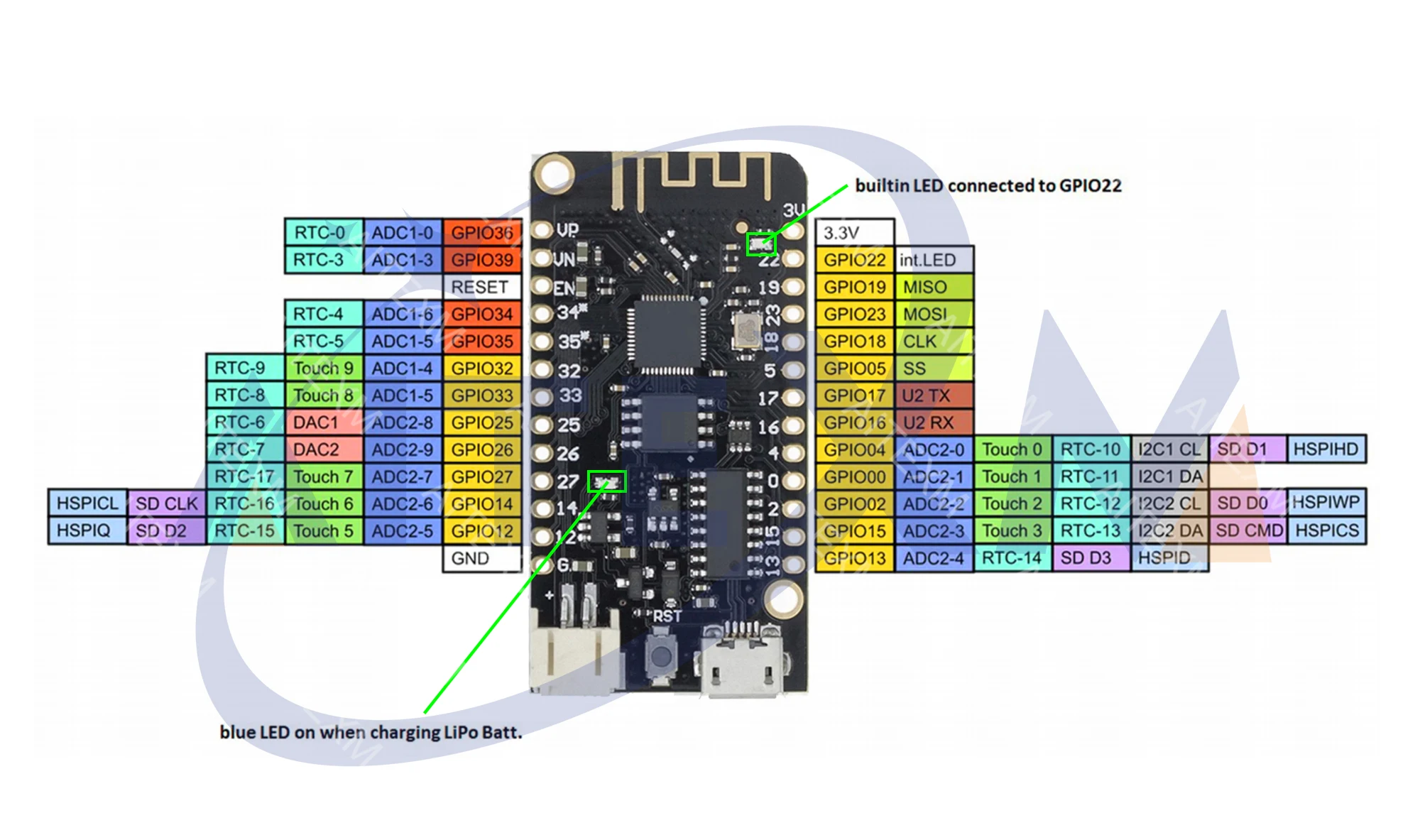
ESP32 plus 18650. With power switch. A blue LED on GPIO16.
| VCC | GND |
| EN | 23 (SPI MOSI) |
| SVP (GPIO 36) | 22 (I2C SCL) |
| SVN (GPIO 39) | TX |
| 34 | RX |
| 35 | 21 (I2C SDA) |
| 32 | GND |
| 33 | 19 (SPI MISO) |
| 25 | 18 (SPI CLK) |
| 26 | 5 (SPI CS) |
| 27 | 17 (TX2) |
| 14 | 16 (RX2) |
| 12 | 4 |
| GND | 0 |
| 13 | 2 |
| SD2 (GPIO 9) | 15 |
| SD3 (GPIO 10) | SD1 (GPIO 8) |
| CMD (GPIO 11) | SD0 (GPIO 7) |
| 5V | CLK (FLASH) |
| NC | NC |
SD0 (GPIO 7), SD1 (GPIO 8), SD2 (GPIO 9), SD3 (GPIO 10), and CMD (GPIO 11) are connected to the internal FLASH. SVP (GPIO 36) and SVN (GPIO 39) are input only. TX (GPIO 1) and RX (GPIO 3) are the default serial.
EN is the 3.3V regulator's enable pin. It's pulled up, so connecting to ground disables the 3.3V regulator. This means that you can use this pin connected to a pushbutton to restart the ESP32. Or just push the EN button on the board.
I did need to install the ESP32 toolchain from Espressif for one project. This was straightforward on a Mac running OSX. Simply follow the instructions at espressif.com. I needed an older version of the toolchain for the project, which was no problem as espressif keep the previous versions available for just such issues.
The Espressif toolchain is a good old traditional command line system with complier, linker, and make. Easy for some-one comfortable with Unix command line environments. Perhaps a challenge for some-one used to graphical development environments.
To use I2C with these ESP32 modules you're likely to need to map some GPIO pins to the I2C bus. These new pin definitions are then passed to the Arduino Wire library begin function in setup. You must take care to use pins that are I/O rather than Input only. Check the datasheet. The T-Display board uses 21/22 for SDA/SCL I2C, which is the Arduino default, but the POE board doesn't break out those pins.
For example, on the POE board the expansion connector is:
| Pin | Function | Pin | Function |
|---|---|---|---|
| 36 | Input | 39 | Input |
| 34 | Input | 35 | Input |
| 16 | Input/Output | 32 | Input/Output |
| 33 | Input/Output | 12 | Input/Output |
| 04 | Input/Output | 15 | MOSI |
| 02 | MISO | 14 | SCLK |
So to use I2C we must select two pins and pass that to the Wire library. We can't use the top four pins (36,39,34,35) because they're input only. There are three pins used for SPI (02,14,15) so they're also not available. Any of the remaining pins can be used (16,32,33,12,04).
The code would include something like this:
#include <Wire.h>

// Pins used for i2c
#define I2C_SDA 33
#define I2C_SCL 32

void setup()
{
  Wire.begin(I2C_SDA,I2C_SCL);
}
SPI is often used for LCD displays. The pin names used by the ESP32 boards do not always match the pin names used on the LCD displays.
| Name | Description |
|---|---|
| MISO | Master In, Slave Out |
| MOSI | Master Out, Slave In |
| SCK | Serial Clock |
| CS | Chip Select |
| Name | Description |
|---|---|
| SCL | Serial Clock |
| SDA | Serial Data |
| CS | Chip Select |
| RST | Reset |
| DC | Data Command |
| BLK | Backlight |
Because most displays are write only, we don't need MISO, only MOSI. Connect MOSI to SDA, SCK to SCL, CS to CS. The RST, DC, and BLK pins can connect to any available GPIO output. These typically get defined in your code or the library being used.